What is architectural drawing?
Short answer
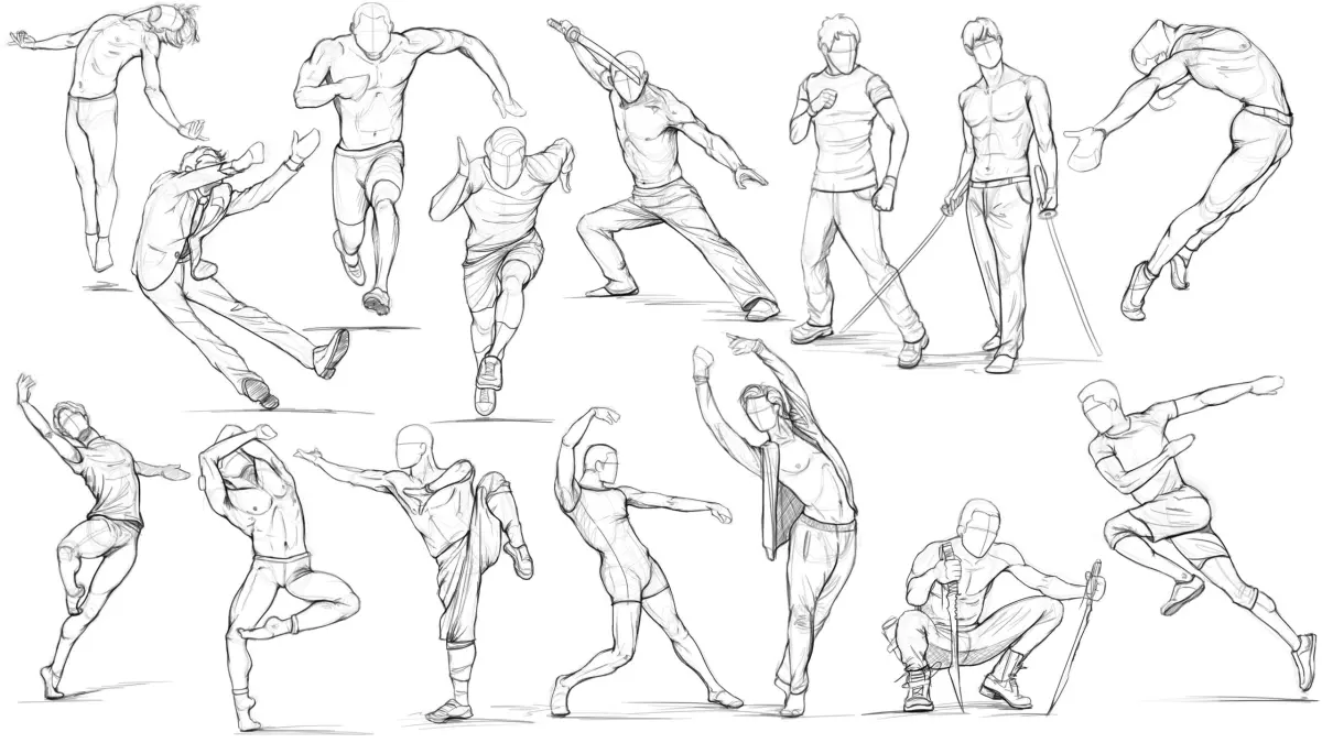
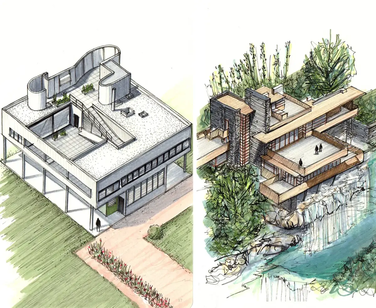
Architectural drawing is the technical and artistic practice of creating precise visual representations of buildings and structures. These documents communicate design intent, structural requirements, and spatial relationships to clients, engineers, and construction teams. By utilizing standardized symbols and projections, architects translate complex three-dimensional concepts into actionable two-dimensional instructions for physical assembly.
On this page
Why is architectural drawing important?
Architectural drawings serve as the primary language of the construction industry, bridging the gap between an abstract idea and a finished building. Without these detailed plans, it would be impossible to ensure structural integrity, adhere to building codes, or coordinate the complex systems—such as plumbing, electrical, and HVAC—that modern buildings require. Every line on a blueprint represents a specific material, dimension, or assembly method.
Beyond technical utility, these drawings act as a legal contract between the architect and the client. They define the scope of work, the quality of materials, and the exact placement of structural elements. By providing a clear roadmap, drawings mitigate the risk of costly errors on the job site, ensuring that all tradespeople work from the same set of accurate, approved information.
What are the types of architectural drawings?
Architectural documentation typically follows a hierarchy of views, each serving a distinct purpose during the design and construction phases. Architects use specific drawing types to convey different levels of detail, ranging from broad conceptual layouts to microscopic construction specifications.
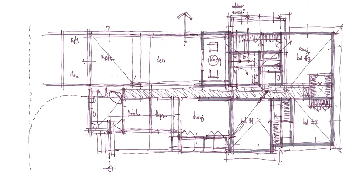
- Floor plans: Top-down views showing the layout of rooms and walls.
- Elevations: Flat, two-dimensional views of the building's exterior facades.
- Sections: Vertical slices through the building to show interior heights and materials.
- Site plans: Diagrams showing the building's location relative to property lines and topography.
- Detail drawings: Large-scale views of specific joints or complex construction assemblies.
These documents are often organized into a "set," which acts as a comprehensive manual for the structure. While digital software is the industry standard today, the core principles of projection and scale remain rooted in traditional drafting techniques established centuries ago.
How to read architectural drawings for beginners
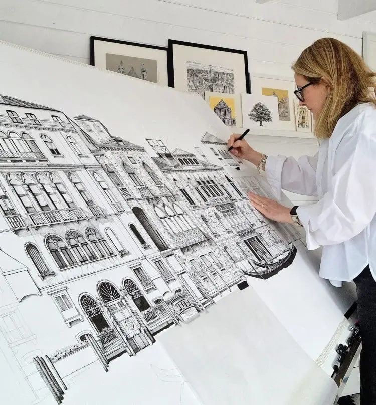
Reading a blueprint requires understanding the standardized language of lines, symbols, and scales. Most drawings are created at a specific scale, such as 1/4 inch equals 1 foot, meaning every quarter-inch on the paper represents one foot of physical space. You must first locate the legend or "key" on the sheet to interpret the specific symbols used for doors, windows, and electrical outlets.
- Locate the North arrow on the site plan to understand the building's orientation.
- Identify the scale bar to verify the proportions of the depicted spaces.
- Cross-reference the floor plan with the section drawings to visualize vertical height.
- Check the revision block in the title box to ensure you are looking at the most current version.
Always look for the "general notes" section, which provides crucial information about material standards and local code requirements that may not be explicitly drawn on the plans.
How to start learning architectural drawing
Developing proficiency begins with mastering the fundamentals of orthographic projection and technical sketching. Beginners should focus on the relationship between plan, section, and elevation views, learning how to project points from one drawing to another to maintain consistency. Practicing with a simple structure, such as a garden shed or a small cabin, allows you to grasp the basics of wall thicknesses and spatial flow.
- Invest in a high-quality mechanical pencil and a set of drafting triangles.
- Practice drawing to scale on grid paper to maintain accurate proportions.
- Study existing sets of residential plans to see how professionals annotate their work.
- Learn the basics of CAD (Computer-Aided Design) software, which is now the primary tool for the profession.
Consistency is key; by sketching daily, you will naturally develop a better understanding of how structures go together and how to represent them clearly on a two-dimensional surface.
Common mistakes when creating architectural drawings
One of the most frequent errors in drafting is inconsistent line weights, which makes it difficult for contractors to distinguish between structural walls and minor partitions. A heavy line usually denotes a cut through a structural element, while thinner lines represent fixtures or surface finishes. Failing to establish a clear hierarchy of line weights leads to cluttered, confusing documents that are prone to misinterpretation during construction.
Another common pitfall is neglecting to include sufficient dimensions or referencing. If a contractor has to "scale" a drawing with a ruler to find a measurement, the drawing is considered incomplete and dangerous. Always ensure that every critical dimension is explicitly written out. Additionally, failing to update all related drawings after a design change is a major oversight; if you move a wall on the floor plan, you must immediately update the corresponding section and elevation views to prevent discrepancies. Precision and thoroughness are the hallmarks of a professional set of plans.
Key facts
- Architectural drawings are technical representations of buildings that communicate design intent to contractors, engineers, and clients.
- The standard scale for floor plans is typically 1/8 inch equals 1 foot or 1/4 inch equals 1 foot in imperial measurements.
- Orthographic projection is the primary method used, showing the building from top, side, and front views without perspective distortion.
- A complete set of construction documents, often called "blueprints," includes floor plans, elevations, sections, and site plans.
- Architects traditionally used drafting tables and vellum, but most modern professional work is completed using Computer-Aided Design (CAD) software.
- Always include a north arrow, a clear legend for symbols, and a comprehensive title block on every sheet to ensure clarity and professional standards.
The bottom line
Architectural drawing serves as the essential language of the building industry, transforming abstract concepts into precise, actionable instructions. By mastering orthographic projections, standard scales, and clear notation, designers ensure that complex structures can be safely and accurately realized. Whether through traditional manual drafting or digital modeling, these drawings remain the primary bridge between a creative vision and the physical reality of a finished building.
People also ask
What is the difference between a floor plan and a site plan?
A floor plan is a horizontal cross-section of a building showing walls, doors, and room layouts from above. A site plan shows the entire property, including the building's footprint, landscaping, driveways, and property boundaries in relation to the surrounding land.
Why do architects use sections in their drawings?
Sections show a vertical cut through a building, revealing the internal construction, ceiling heights, and material layers. This view is essential for understanding how different levels of a structure connect and how materials are layered within the walls and floors.
What is an elevation drawing?
An elevation is a flat, two-dimensional view of one side of a building's exterior. It shows the height, window placement, roof pitch, and exterior finishes without any perspective depth, serving as a guide for how the building will look from the outside.
What are construction documents?
Construction documents are the final, legal set of drawings and specifications used to obtain building permits and guide the actual construction process. They provide the precise dimensions and technical details necessary for builders to construct the project exactly as designed.
How do I avoid common mistakes in architectural drafting?
A frequent error is inconsistent line weights, which make drawings difficult to read. Always use thicker lines for walls being cut through and thinner lines for surface details or furniture to create visual hierarchy and depth.
What is the purpose of a title block?
The title block is a standard rectangular area, usually placed on the right side or bottom of a drawing sheet. It contains vital information such as the project name, sheet title, scale, date, and the architect’s contact information to ensure proper document management.
This answer was created with the help of AI research tools and reference sources. Spotted an error? Let us know — we correct mistakes quickly. See our editorial policy.