What is technical drawing?
Short answer
Technical drawing is a precise, standardized method of visual communication used to convey the design, dimensions, and assembly requirements of objects. Unlike artistic sketches, these drawings provide exact specifications for manufacturing, architecture, and engineering. They utilize universal symbols and geometric projections to ensure that any qualified professional can interpret the design accurately.
On this page
What is the purpose of technical drawing?
Technical drawing serves as the primary language of industry, bridging the gap between a conceptual idea and a physical product. By adhering to strict international standards, such as those set by the International Organization for Standardization (ISO) or the American Society of Mechanical Engineers (ASME), these documents eliminate ambiguity. They ensure that a part designed in one country can be manufactured with perfect precision in another.
The core objective is to provide a complete set of instructions for fabrication. A technical drawing identifies the exact geometry, material properties, tolerances, and surface finishes required for an object. Without these rigorous standards, complex infrastructure like bridges, airplanes, and microchips would be impossible to build safely or reliably. It transforms abstract thoughts into actionable data, serving as a legal and technical contract between designers and builders.
How do you read a technical drawing?
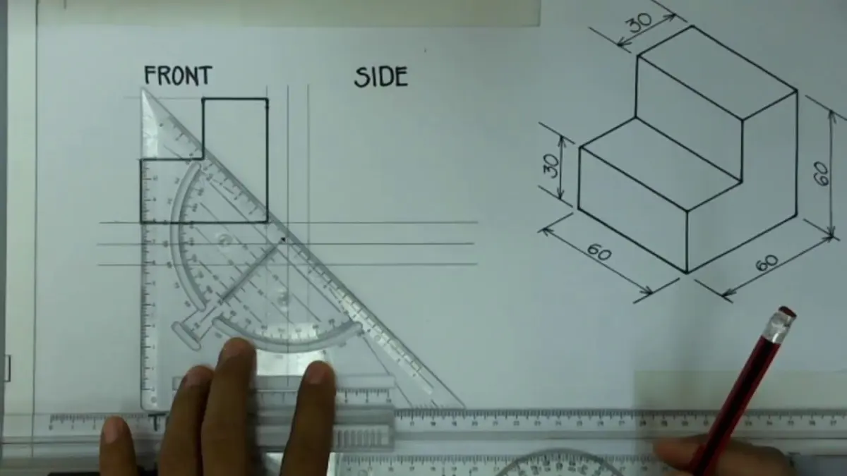
Reading a technical drawing requires an understanding of specific conventions, primarily orthographic projection. This technique represents a three-dimensional object by showing it from multiple two-dimensional perspectives, typically the front, top, and side views. These views are aligned precisely on the page to allow the viewer to mentally reconstruct the object's depth and form.
To interpret a drawing effectively, one must look for several key components:
- Title block: Contains the drawing name, scale, date, and revision history.
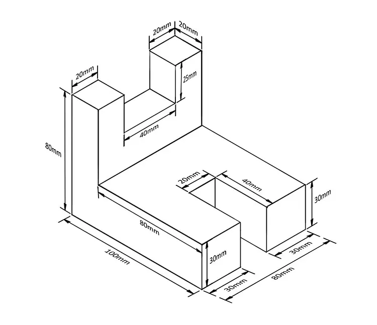
- Dimension lines: Indicate the physical size of the object using arrows and numerical values.
- Section views: Show the interior of an object by "cutting" through it to reveal hidden details.
- Leader lines: Connect notes or labels to specific features on the drawing.
- Tolerances: Specify the allowable variation in size to ensure parts fit together correctly.
What are the common tools for technical drawing?
Historically, technical drawing was performed on drafting tables using physical tools to ensure geometric accuracy. While digital software has become the industry standard, understanding these traditional instruments remains fundamental for grasping spatial relationships. Precision is the ultimate goal, and every tool is designed to maintain consistency across the entire document.
Key instruments utilized in manual drafting include:
- T-squares and parallel bars: Used to draw perfectly horizontal lines across the drafting board.
- Triangles: Provide fixed angles, such as 30, 45, and 60 degrees, for consistent geometry.
- Compasses: Essential for creating accurate circles and arcs of specific radii.
- Drafting scales: Specialized rulers that allow designers to draw objects at a reduced or enlarged proportion.
- Dividers: Used for transferring measurements from one location to another without error.
Why is accuracy critical in technical drawing?
Accuracy in technical drawing is not merely a matter of aesthetics; it is a matter of safety and economic viability. Even a minor error in a dimension or a misinterpreted symbol can lead to catastrophic failure in mechanical systems or structural collapse in construction. When a drawing specifies a tolerance of 0.01 millimeters, the manufacturing equipment must meet that exact standard to ensure the final assembly functions as intended.
Common mistakes that lead to inaccuracies include:
- Failing to account for material thickness in sheet metal designs.
- Misinterpreting the scale, leading to parts that are too large or small.
- Omitting critical dimensions, forcing the manufacturer to guess the intended size.
- Using non-standard symbols that confuse the fabricator or lead to misinterpretation.
- Neglecting to update the revision block, which results in builders using outdated, incorrect specifications.
How do you start learning technical drawing?
Learning technical drawing begins with mastering the basics of geometry and spatial visualization. Beginners should start by practicing hand-drawing simple geometric shapes using a pencil and a straightedge to develop a steady hand and an eye for proportion. Once the fundamentals of orthographic projection are understood, students often transition to Computer-Aided Design (CAD) software, which automates many of the repetitive tasks involved in drafting.
To progress efficiently, follow these steps:
- Study the principles of line weights, where thicker lines represent visible edges and thinner lines represent dimensions or centerlines.
- Practice "sketching to scale" on grid paper to train your brain to visualize proportions without relying on software.
- Learn to read existing blueprints or technical manuals to see how professionals document complex assemblies.
- Enroll in introductory courses focusing on geometric dimensioning and tolerancing (GD&T) to understand how to specify functional requirements.
- Build a portfolio of simple parts, documenting them from multiple angles to demonstrate your growing mastery of the language of engineering.
Key facts
- Technical drawing, also known as drafting, is the precise act of composing plans and schematics for buildings, machines, and circuits.
- The International Organization for Standardization (ISO) establishes global rules, such as ISO 128, to ensure drawings are interpreted identically worldwide.
- Orthographic projection is the most common technique, representing a three-dimensional object as a series of two-dimensional views like top, front, and side.
- Modern drafting relies heavily on Computer-Aided Design (CAD) software, which replaced traditional manual tools like T-squares and compasses in the 1980s.
- Dimensioning is the most critical step, as it provides the exact measurements required for manufacturing or construction without needing scale measurement.
- A common mistake is failing to include a clear title block, which identifies the scale, material, revision number, and the engineer responsible for the design.
The bottom line
Technical drawing serves as the universal language of engineering and manufacturing, bridging the gap between a conceptual idea and a physical reality. By adhering to strict international standards and utilizing precise geometric projections, drafters provide the exact instructions needed to build complex systems. Mastering this skill requires a focus on accuracy, clear notation, and the logical organization of spatial information to ensure successful project execution.
People also ask
What is the difference between a technical drawing and an artistic sketch?
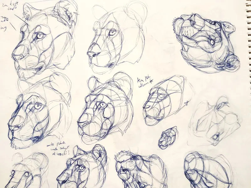
An artistic sketch focuses on aesthetics and personal expression, whereas a technical drawing prioritizes accuracy, standardized symbols, and clear communication for construction. Technical drawings must be reproducible and unambiguous to ensure that a part produced in one country matches a design created in another.
What tools are essential for manual technical drawing?
Essential tools include a drafting board, T-square or parallel bar, triangles for 30, 45, and 60-degree angles, and high-quality mechanical pencils. Compasses are used for precise circles, while dividers help transfer exact distances between different parts of the drawing.
What is a "section view" in a technical drawing?
A section view represents an object as if it has been cut open to reveal its internal features. This technique is vital for showing hidden cavities, wall thicknesses, or complex internal mechanisms that are not visible from the outside.
How do I choose the right scale for a drawing?
The scale should be chosen so the object fits comfortably on the paper while allowing enough space for dimensions and notes. Common scales include 1:1 for full size, 1:10 for reduction, and 2:1 for enlargement of small, intricate parts.
Why are line weights important in drafting?
Line weights define the hierarchy of information, with thick lines representing visible outlines and thin lines indicating dimensions or centerlines. Using consistent line weights prevents visual clutter and ensures the most important structural elements stand out clearly.
What is the purpose of a bill of materials (BOM)?
A bill of materials is a comprehensive list of all parts, raw materials, and components required to construct the assembly shown in the drawing. It acts as a procurement guide and ensures that all necessary items are accounted for before production begins.
This answer was created with the help of AI research tools and reference sources. Spotted an error? Let us know — we correct mistakes quickly. See our editorial policy.