What is orthographic drawing?
Short answer
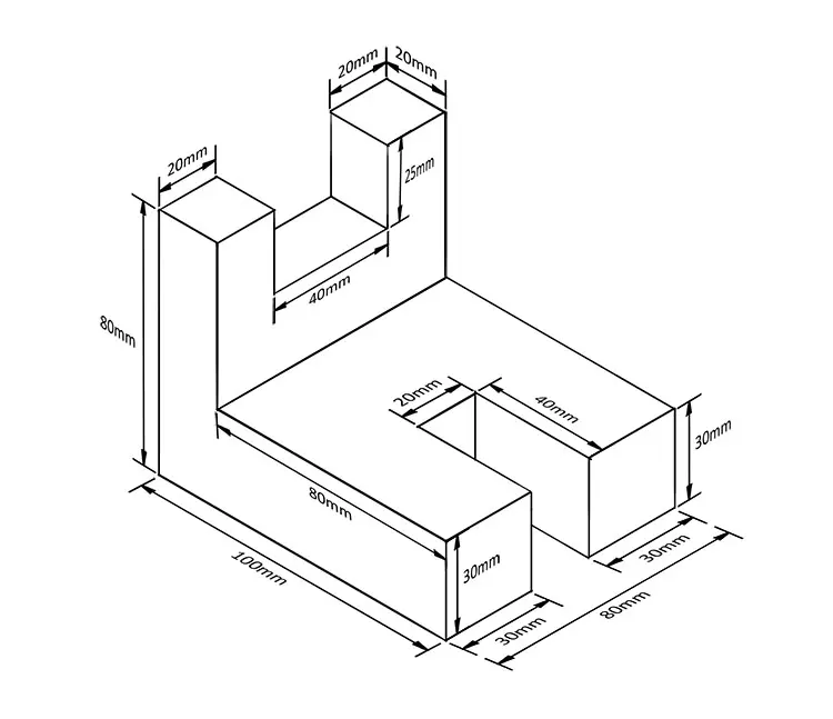
Orthographic drawing is a technical illustration method that represents a three-dimensional object as a series of two-dimensional views. By projecting the object onto flat planes, it provides precise measurements and geometric details. Engineers and architects use this standard system to communicate complex designs clearly without the distortion inherent in perspective drawings.
On this page
What is the purpose of orthographic drawing?
Orthographic drawing serves as the universal language of engineering, manufacturing, and construction. Its primary purpose is to provide an unambiguous, scale-accurate representation of an object’s physical dimensions. Unlike artistic sketches that use vanishing points to simulate depth, orthographic projections maintain true proportions by aligning the viewer’s line of sight perpendicular to the object's surfaces.
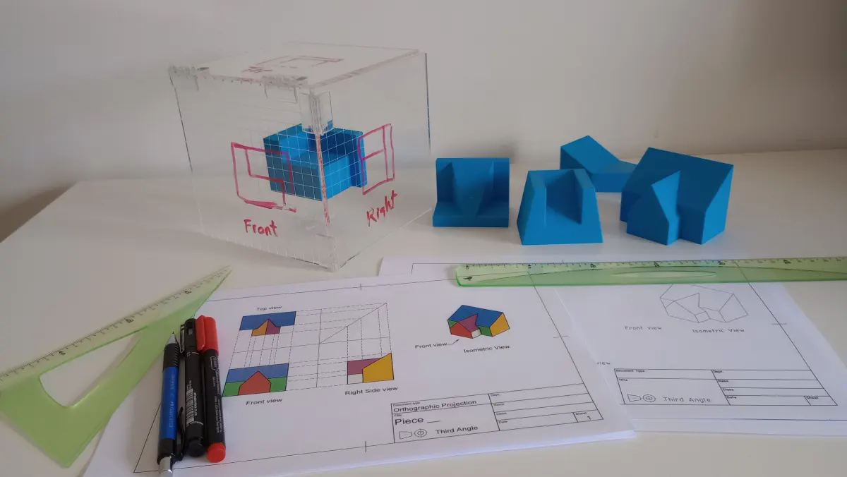
This method allows designers to document every facet of a component, including internal features that might otherwise remain hidden. By breaking a complex form into distinct views—typically the top, front, and side—the drawing eliminates guesswork for builders. It ensures that a part designed in one country can be manufactured accurately in another, as the standardized rules of projection remain consistent across global industries.
How do you create an orthographic projection?
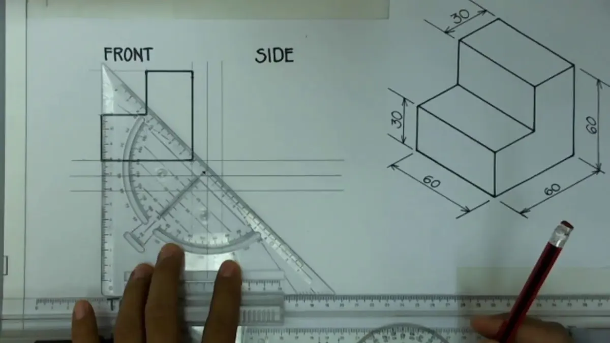
Creating an orthographic drawing requires a systematic approach to spatial visualization. The process involves "unfolding" the object into a two-dimensional plane, ensuring that all views remain perfectly aligned with one another. Consistency in alignment is the most critical aspect of the technique, as it allows the reader to cross-reference dimensions between different views.
- Select the front view, which should be the side that reveals the most detail or the object's primary shape.
- Project lines horizontally and vertically from the front view to establish the boundaries of the top and side views.
- Use a 45-degree miter line to transfer depth measurements from the top view to the side view, ensuring the width and depth remain proportional.
- Add center lines to indicate symmetry and hidden lines to represent internal features that are not visible from the outside.
Why is third-angle projection used?
In the United States and Canada, third-angle projection is the standard convention for technical drawings. In this system, the object is placed behind the projection plane, and the viewer looks through the plane to see the object. This results in the top view being placed above the front view, and the right-side view being placed to the right of the front view.
Conversely, first-angle projection is commonly used in Europe and much of Asia. In this system, the object is placed in front of the projection plane, effectively flipping the views. Understanding the difference is vital because misinterpreting the projection type can lead to catastrophic errors in manufacturing. Engineers must always include a projection symbol in the title block of the drawing to inform the reader which standard is being applied to the technical documentation.
What are the common mistakes when drawing orthographic views?
Even experienced drafters can struggle with the strict spatial requirements of orthographic projection. One of the most frequent errors is the failure to maintain alignment between views. If the top view is shifted even slightly to the left or right of the front view, the drawing loses its mathematical integrity and becomes difficult to interpret.
- Forgetting to include hidden lines for internal holes or recessed features.
- Mislabeling the scale, which renders the dimensions useless for actual fabrication.
- Overcrowding the drawing with unnecessary dimensions that lead to visual clutter.
- Neglecting to use the correct line weights, such as thick lines for visible edges and dashed lines for hidden ones.
- Failing to include a clear title block, which identifies the part name, material, and the specific projection angle used.
Best tools for orthographic drawing beginners
For those just beginning to learn technical drafting, starting with traditional manual tools is highly recommended. Using a drafting board, a T-square, and triangles helps develop a fundamental understanding of how lines relate to one another in space. This tactile experience creates a stronger mental connection to the geometry than jumping straight into digital software, where the computer often performs the projection automatically.
- A high-quality mechanical pencil with 0.5mm lead for consistent line width.
- A set of 30-60-90 and 45-degree triangles for drawing precise angles.
- A drafting compass for creating accurate circular features and arcs.
- A scale ruler to ensure that the drawing is proportional to the actual object size.
- Drafting tape to secure the paper to the board, preventing movement during the layout process.
Once these manual skills are mastered, transitioning to computer-aided design software becomes significantly more intuitive. Digital tools automate the projection process, but the underlying principles of orthographic representation remain identical to those used on the drafting board.
Key facts
- Orthographic drawing represents a three-dimensional object in two dimensions using multiple flat views.
- The standard views used are the top, front, and right-side projections.
- These drawings rely on parallel projection lines to maintain accurate scale and proportions.
- The technique is the primary language of engineering, architecture, and manufacturing industries.
- Hidden lines are represented by dashed lines to show internal features not visible from the outside.
- Always align views horizontally and vertically to ensure the drawing remains readable and accurate.
The bottom line
Orthographic drawing is a fundamental technical skill that translates complex 3D forms into precise, measurable 2D planes. By systematically projecting views, designers can communicate exact specifications for manufacturing and construction without the distortions of perspective. Mastering this method requires strict attention to alignment, line types, and scaling, ensuring that every detail of an object is clearly understood by engineers, builders, and fabricators alike.
People also ask
How does orthographic projection differ from perspective drawing?
Perspective drawing mimics how the human eye sees objects by converging lines toward a vanishing point, which distorts dimensions. Orthographic projection keeps lines parallel, ensuring that measurements remain true to scale for construction.
What is the purpose of a multi-view drawing?
A multi-view drawing provides a complete description of an object's shape and size from different angles. This prevents ambiguity during the manufacturing process by showing details that might be hidden in a single view.
What is the difference between first-angle and third-angle projection?
These are two global standards for arranging views. Third-angle projection is standard in the United States, placing the top view above the front view, while first-angle projection is common in Europe and places the top view below the front view.
What are common mistakes when creating orthographic drawings?
A frequent error is failing to align the views correctly, which makes it difficult to interpret the object's dimensions. Another mistake is omitting hidden lines or center lines, which are essential for defining circular features and internal geometry.
Do I need special tools to create these drawings?
While CAD software is the modern standard, you can create accurate orthographic drawings using a drafting board, T-square, triangles, and a compass. The focus should always be on maintaining precise 90-degree relationships between the projection planes.
How do I know which views to include?
You should include only the minimum number of views necessary to fully define the object. If an object is simple, two views may suffice, but complex parts usually require the standard three views plus an auxiliary view if slanted surfaces exist.
This answer was created with the help of AI research tools and reference sources. Spotted an error? Let us know — we correct mistakes quickly. See our editorial policy.