What is isometric drawing?
Short answer
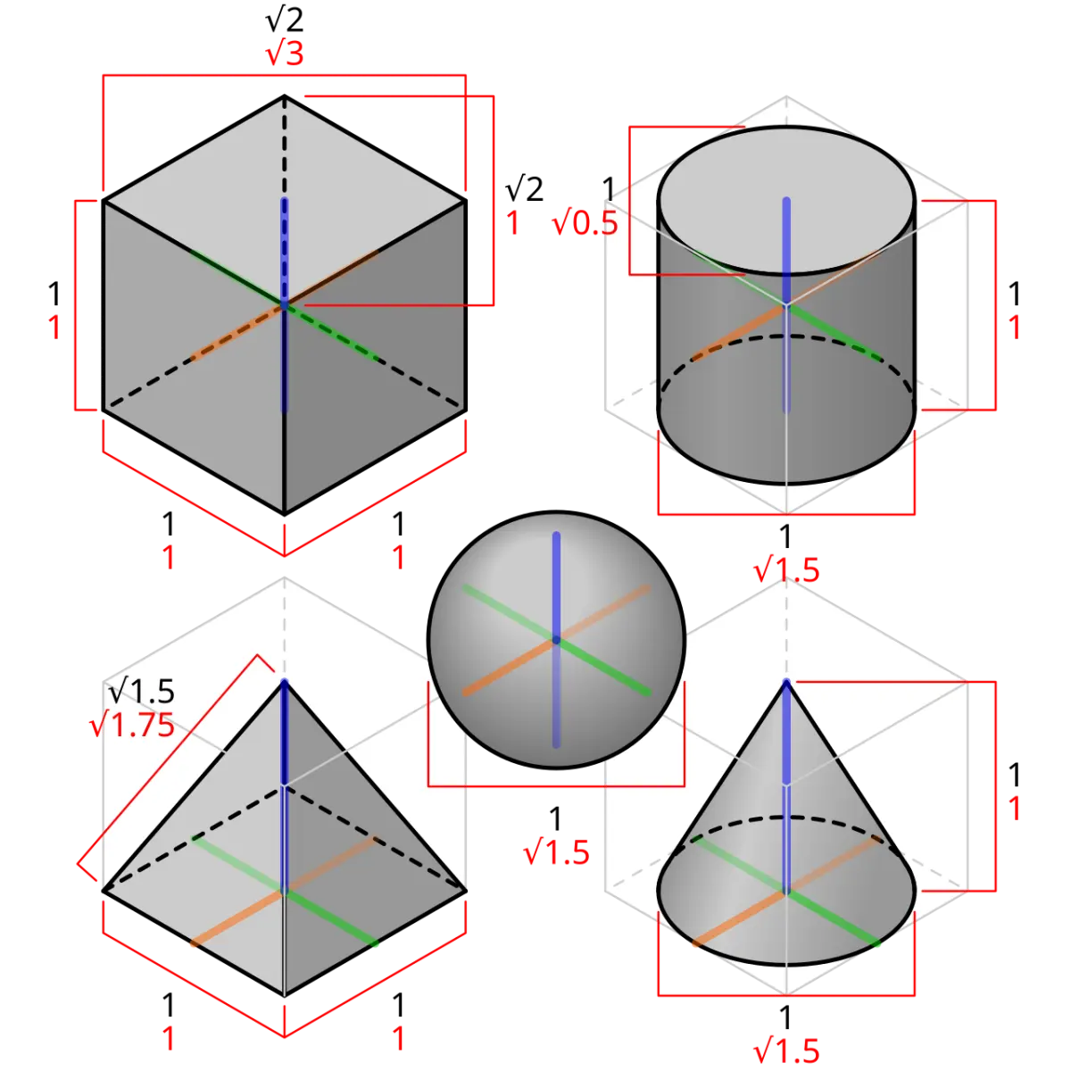
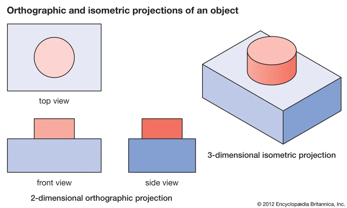
Isometric drawing is a method of visual representation that depicts three-dimensional objects in two dimensions while maintaining a constant scale. It uses a 120-degree angle between the three primary axes, ensuring that vertical lines remain vertical and horizontal lines recede at 30-degree angles. This technique provides a clear, measurable view of complex structures.
On this page
What is isometric drawing used for?
Isometric drawing is a specialized form of axonometric projection used primarily in engineering, architecture, and industrial design. Unlike perspective drawing, which uses vanishing points to create the illusion of depth, isometric projection keeps parallel lines parallel. This ensures that measurements taken along the three main axes—width, height, and depth—remain true to scale. Because of this mathematical consistency, engineers and drafters use it to create technical illustrations that allow for accurate interpretation of dimensions without the distortion found in standard perspective views.
Beyond technical drafting, the style has become a staple in video game design and graphic illustration. Designers favor isometric views because they offer a clear, "god-eye" perspective of a scene, making it easier to arrange complex environments or game boards. By avoiding the complexities of foreshortening, creators can build modular assets that fit together perfectly. This consistency is essential for maintaining spatial logic in digital interfaces and technical manuals where clarity is more important than artistic realism.
How to create an isometric drawing
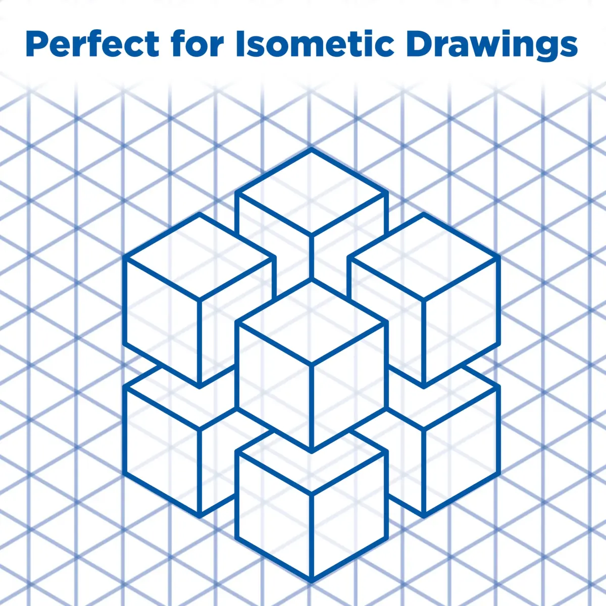
Creating an isometric drawing requires a systematic approach to maintain the correct orientation of the object’s edges. The fundamental rule is that the three principal axes are separated by 120 degrees. When working on paper, drafters typically use an isometric grid or a 30-60-90 degree triangle to ensure precision. The process involves establishing a starting point and building the object outward along these defined paths, ensuring that every line follows the isometric grid.
- Start by drawing a vertical line to represent the height of the object.
- Draw two lines extending from the base of the vertical line at 30-degree angles to the horizontal plane to define the width and depth.
- Use these three lines as the foundation to build the rest of the object, ensuring all parallel edges remain parallel to the initial axes.
- Add detail lines by measuring distances along the established axes, keeping the scale consistent throughout the entire drawing process.
- Finalize the drawing by darkening the object lines and erasing any construction marks or grid lines that are not part of the final design.
Best tools for isometric drawing
For beginners, the most effective tool is isometric grid paper. This paper is pre-printed with a network of triangles, which eliminates the need to manually measure angles for every line. When using this paper, you can align your ruler with the printed lines to maintain the 30-degree slope effortlessly. This tool is invaluable for learning the spatial relationships required for the technique and helps prevent the most common alignment errors that occur during the initial sketching phase.
For those moving into professional or digital work, specialized software is the preferred choice. Computer-aided design (CAD) programs like AutoCAD or vector-based software like Adobe Illustrator provide built-in isometric grids and snapping tools. These features allow the user to draw shapes that automatically lock to the isometric axes, significantly increasing speed and accuracy. Whether using physical drafting tools or digital platforms, the goal remains the same: ensuring that the 120-degree relationship between the axes is never compromised, as even a slight deviation will make the object appear distorted to the viewer.
Common mistakes when drawing isometrically
A frequent error in isometric drawing is the accidental use of perspective. Beginners often feel an urge to make lines converge toward a vanishing point, which destroys the isometric property of the drawing. If lines are not perfectly parallel to the primary axes, the object will appear warped or "off." Another common mistake involves the representation of circles and curves. In an isometric view, a circle must be drawn as an ellipse, but many drafters incorrectly draw it as a simple circle, which results in an unnatural appearance that conflicts with the surrounding geometry.
To avoid these pitfalls, keep the following tips in mind:
- Always verify that all horizontal edges are drawn at a 30-degree angle to the horizon line.
- Never allow parallel lines to converge, regardless of how far back they recede in the drawing.
- Use an "isometric ellipse" template or construction box to plot curves, as these are mathematically distinct from standard circles.
- Double-check your measurements along the axes, as it is easy to lose track of scale when working on complex, multi-part objects.
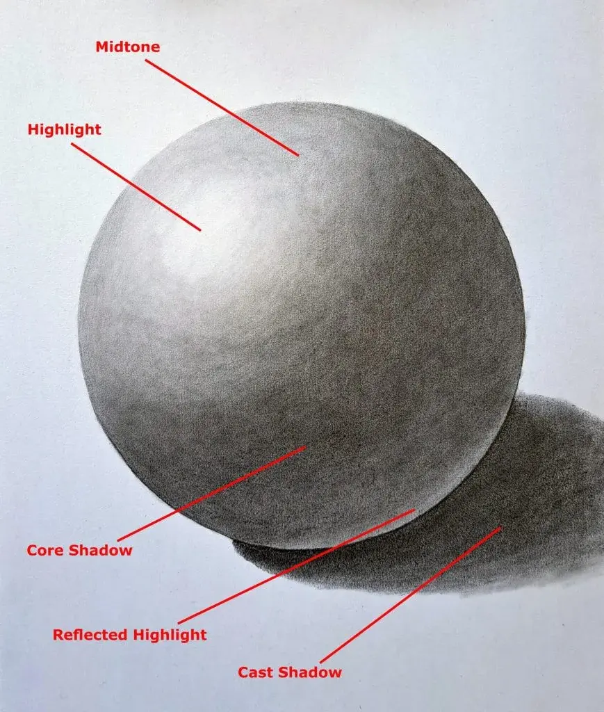
- Maintain a consistent light source if you are adding shading, as the isometric view can make depth cues confusing if shadows are placed inconsistently.
Why isometric drawing is different from perspective
The primary difference between isometric drawing and perspective drawing lies in the concept of foreshortening. In perspective drawing, objects appear smaller as they move further away from the viewer, mimicking the way the human eye perceives the world. This creates a realistic but non-measurable image. Isometric drawing ignores this effect entirely, treating all parts of the object as if they are at an equal distance from the observer. This makes the drawing an analytical tool rather than a representational one, as it prioritizes data over visual mimicry.
This distinction is vital for industries where precision is paramount. If you are designing a mechanical part, you need to be able to read the length and width directly from the drawing without having to calculate the perspective distortion. While perspective drawing is superior for artistic expression and architectural renderings meant to show how a building looks to a passerby, isometric drawing is the industry standard for assembly instructions, patent filings, and mechanical blueprints. By removing the human element of sight from the equation, isometric drawing provides a universal language for engineers and designers to communicate the exact physical dimensions of their creations.
Key facts
- Isometric drawing is a method of visual representation where all three axes appear equally foreshortened at 120-degree angles.
- The term "isometric" originates from the Greek words "isos" (equal) and "metron" (measure), reflecting the consistent scale used across all dimensions.
- Unlike perspective drawing, parallel lines in an isometric view remain parallel and do not converge at a vanishing point.
- Professor William Farish of Cambridge University is widely credited with formalizing the principles of isometric projection in 1822.
- Use a 30-degree set square when drafting on paper to ensure the horizontal lines maintain the correct isometric angle.
- Avoid drawing circles as perfect rounds; in isometric projection, circles must be drawn as ellipses to account for the tilted plane.
The bottom line
Isometric drawing serves as a vital technical tool that translates three-dimensional concepts into clear, measurable two-dimensional images. By maintaining parallel lines and consistent scaling, it provides an objective view that is indispensable for engineers, architects, and game designers. Mastering the 120-degree axis and the proper construction of ellipses ensures that your technical illustrations remain accurate, professional, and easy for others to interpret during the construction phase.
People also ask
How does isometric drawing differ from perspective drawing?
Perspective drawing uses vanishing points to create the illusion of depth, meaning objects appear smaller as they move further away. Isometric drawing maintains a constant scale, so an object's size remains identical regardless of its distance from the viewer.
Why is isometric drawing popular in engineering and architecture?
It allows professionals to communicate complex three-dimensional designs on a two-dimensional surface without distortion. Because measurements remain accurate, builders can easily calculate material requirements and visualize assembly processes directly from the drawing.
Can you draw curves in an isometric view?
Yes, but they must be constructed using the four-center ellipse method to maintain geometric accuracy. You define a rhombus in the isometric plane and use its midpoints to plot the arcs that form the ellipse.
Is isometric drawing used in modern video games?
Many strategy and simulation games utilize an isometric perspective to provide a clear, static view of the game world. This style allows players to see multiple units and structures simultaneously without the camera movement required by 3D engines.
What are the most common mistakes beginners make?
Beginners often forget to keep vertical lines perfectly vertical or fail to maintain the 120-degree separation between axes. Another frequent error is drawing circles as simple rounds instead of ellipses, which ruins the perceived depth of the object.
Do I need specialized software to create isometric drawings?
While CAD programs like AutoCAD or SolidWorks offer automated isometric tools, you can create them using basic vector software or traditional drafting tools. The essential requirement is a grid or a set square to ensure all lines adhere to the 30-degree projection rule.
This answer was created with the help of AI research tools and reference sources. Spotted an error? Let us know — we correct mistakes quickly. See our editorial policy.