How do you draw a cogwheel?
Short answer
Drawing a cogwheel requires creating a circle for the pitch diameter and spacing identical teeth along its perimeter. By establishing a center point and using a compass or protractor, you ensure mathematical precision. Each tooth follows a specific profile, typically an involute curve, which allows gears to mesh smoothly without binding.

On this page
How to draw a basic cogwheel shape
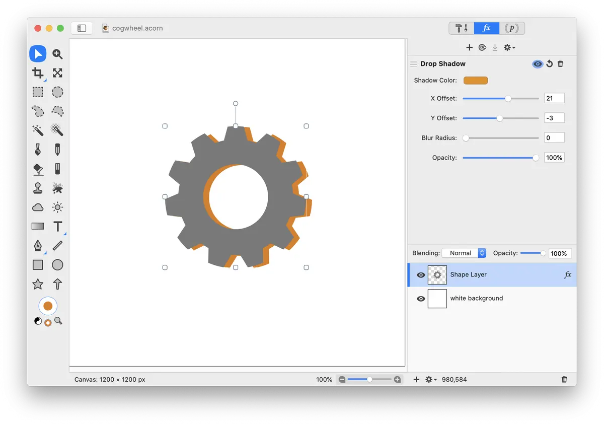
To draw a cogwheel, start by defining the structural circles that govern its geometry. You need three concentric circles: the addendum circle (the outer tips of the teeth), the pitch circle (the middle line where teeth mesh), and the dedendum circle (the base of the teeth). Use a compass to draw these lightly on your paper, as they serve as your primary construction guides for spacing.
Once the circles are set, divide the circumference into equal segments to determine the number of teeth. Use a protractor to mark these divisions precisely. If you want 12 teeth, for example, place a mark every 30 degrees around the circle. These marks will act as the center lines for each tooth, ensuring that your cogwheel looks symmetrical and functions visually as a mechanical component rather than a random shape.
How to design accurate gear teeth
The shape of the tooth is critical for the mechanical realism of your drawing. While simple triangles are often used for sketches, the industry standard is the involute curve. This curve allows the teeth to roll against each other rather than sliding, which reduces wear in real-world machinery. To draw this, you can simplify the curve into a slight outward arc on both sides of the tooth.
- Mark the width of the tooth on the pitch circle.
- Draw a straight line from the dedendum circle to the pitch circle.
- Curve the line outward toward the addendum circle to form the tip.
- Repeat this process for the other side of the tooth, mirroring the arc.
- Connect the tips of the teeth with a small flat line or a rounded cap.
Best tools for drawing gears
For beginners, a mechanical pencil with a 0.5mm lead is ideal because it maintains a consistent line width, which is essential for gear precision. A high-quality compass is the most important tool in your kit; ensure it has a locking mechanism so the radius does not shift while you are drawing the concentric circles. A metal ruler or a clear plastic protractor will help you maintain the accuracy of your angular measurements.
Drafting templates are also excellent resources for those who struggle with freehand curves. These plastic stencils contain pre-cut shapes for various gear sizes and tooth counts. Using a template allows you to focus on the overall assembly of a gear train rather than the tedious process of calculating individual tooth dimensions. If you are aiming for a technical illustration, a fine-liner pen can be used to ink the final lines once the pencil construction is complete.
Why gear teeth binding happens
Binding occurs when the spacing between teeth is inconsistent or the tooth profile is too thick. If your teeth are not perfectly centered on the pitch circle, they will collide rather than slide into the gaps of a mating gear. In a drawing, this is often caused by failing to use a protractor, leading to "crowding" on one side of the wheel. Always verify that the sum of the tooth width and the gap width is uniform throughout the entire circumference.
Another common issue is the depth of the tooth. If the dedendum is too shallow, the teeth will bottom out against each other, preventing rotation. Conversely, if the teeth are too long, they may become fragile or look disproportionate. To avoid these issues, maintain a consistent ratio where the tooth height is roughly 2.25 times the module, which is the ratio of the pitch diameter to the number of teeth. Keeping these proportions balanced will result in a professional, realistic appearance.
Common mistakes when drawing cogwheels
One frequent error is drawing teeth that are perfectly triangular. While this is easy, it is mechanically incorrect because sharp points lack the surface area to transfer force effectively. Another mistake is forgetting the clearance between the gears. Even in a two-dimensional drawing, you must leave a small gap between the tip of one tooth and the root of the mating gear to suggest that the mechanism is functional and not fused together.
- Neglecting to use a center point, which causes the entire gear to look lopsided.
- Drawing an odd number of teeth without accounting for the symmetry of the spokes.
- Using heavy, dark lines for construction circles, which makes the final gear difficult to distinguish.
- Forgetting to draw the central hole or keyway, which makes the gear look like it cannot be mounted to a shaft.
- Failing to erase the construction lines, which clutters the final design and obscures the tooth profile.
By keeping these guidelines in mind, you can transition from simple sketches to complex, engineering-style illustrations that convey both form and function. Always double-check your spacing before inking, as minor errors in the initial layout become very obvious once the teeth are fully rendered and shaded for depth.
Key facts
- A cogwheel, or gear, relies on the involute curve profile to ensure smooth, constant-velocity power transmission between teeth.
- Always use a compass to draw the pitch circle, which represents the theoretical point where two meshing gears make contact.
- The addendum is the radial distance from the pitch circle to the top of the tooth, while the dedendum is the distance to the root.
- Maintain equal spacing between teeth by dividing the pitch circle circumference by the desired number of teeth using a protractor.
- Avoid drawing teeth with pointed tips; they must be slightly flattened or rounded to prevent mechanical interference and stress concentration.
- Use a gear tooth gauge or a CAD template if precision is required for actual mechanical functionality rather than artistic representation.
The bottom line
Drawing a functional cogwheel requires precision, starting with the pitch circle as your primary reference line. By carefully calculating the tooth spacing and utilizing the involute curve for the tooth profiles, you ensure that the gears will engage without binding. Whether drafting for art or engineering, maintaining consistent geometry across all teeth is the most important step to achieving a professional and mechanically sound result.
People also ask
What is the difference between a cogwheel and a sprocket?
A cogwheel features teeth designed to mesh directly with another gear to transmit torque. A sprocket has teeth specifically shaped to engage with a roller chain or a timing belt.
Why do gear teeth often have a curved shape?
The involute curve profile allows gears to maintain a constant speed ratio even if the distance between their centers fluctuates slightly. This geometry minimizes friction and wear during the meshing process.
How do you determine the number of teeth needed for a gear?
The number of teeth is determined by the required gear ratio between the driving and driven gears. For example, a 20-tooth gear driving a 40-tooth gear creates a 2:1 speed reduction.
What is the "pressure angle" in gear design?
The pressure angle is the angle at which the force is transmitted between two meshing teeth. The standard pressure angle for most industrial applications is 20 degrees.
Can I draw a gear without using a compass?
While you can sketch a gear freehand, using a compass is essential for maintaining the concentric circles required for accuracy. Without these guides, the gear will likely be lopsided and fail to rotate smoothly.
What is the "circular pitch" of a gear?
Circular pitch is the distance measured along the pitch circle from a point on one tooth to the corresponding point on the next. It is a critical measurement for ensuring that two gears can successfully mesh together.
This answer was created with the help of AI research tools and reference sources. Spotted an error? Let us know — we correct mistakes quickly. See our editorial policy.